-
Products
-
Solution
Solution
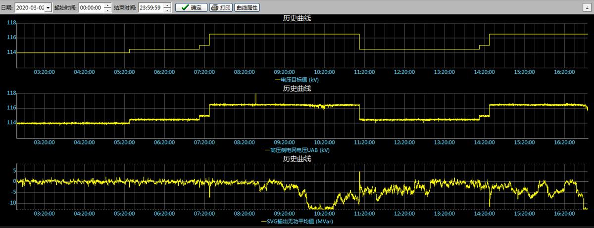
Provide customers with solutions in terms of improving power quality, optimizing control, and energy saving and consumption reduction.
Read more >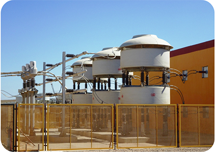
Improving power quality and optimizing control
-
Service
Service
Liaoning Rongxin Xingye Power Technology Co., Ltd. is committed to becoming a reliable partner of customers through honest management. In order to continuously improve the service quality.
Read more >
-
About us
About us
Rongxin Xingye is taking "Rongxin" as the foundation and "Xingye" as its mission, using the wisdom and diligence from China to provide global customers with high-quality products and services to achieve green life and sustainable development.
Read more >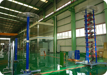
-
Responsibility
Responsibility
"Rongrong grass and trees, longevity of faith", Rongxin Xingye advocates a green lifestyle
Read more >
-
News
News
Focus on energy efficiency and achieve sustainable social development with high-quality products, services and solutions.
Read more >
-
Join us
Join us
Focusing on the development goals of the company's strategic planning, absorbing the essence of corporate culture, and creating a sound, efficient and innovative human resource system.
Read more >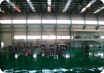
-
Contact us
Contact us
Liaoning Rongxin Xingye Power Technology Co., Ltd. was established in March 2017. It is a high-tech enterprise focusing on the manufacture of energy-saving and high-power power electronic equipment.
Read more >